EPS Fire Flow Analysis Tool
This tool provides the user a way to run an EPS fire flow analysis. The results are presented in a table showing the residual pressure at predefined fire flows at the time of minimum pressure for a given node for the calculated scenario.
How To Use This Tool
The tool is very simple to use and provides minimal options.

When the tool opens, click the Open toolbar button to select a WaterGEMS project to open.
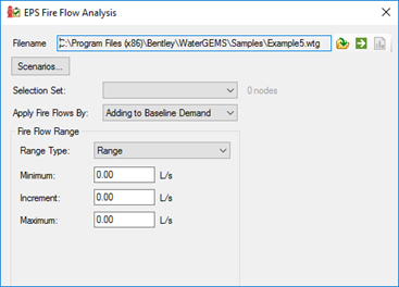
Once the project is open, there are options that must be specified before calculating the EPS Fire Flow.
- Scenarios
- Selection Set
- This option is required.
- The number of fire flow nodes in the selection displays to the immediate right of the drop-down box.
- The number of nodes includes both inactive and active nodes.
- The "Is Active?" state of the node is done during calculations. Inactive elements are ignored.
- Apply Fire Flows By
- Fire Flow Range

Validation
Basic validation is in place to make sure that the minimum settings are specified for a successful run.
- The user must open a valid WaterGEMS model.
- At least one EPS scenario is required.
- A selection set is required.
- If there are no nodes in the selection set then a message is displayed. The number of fire flow nodes in the selection set is displayed immediately to the right of the selection set.
- If there are no active fire flow nodes in the specified selection set, a message is displayed.
- If using the "Range" range type:
Calculations
The hydrant flow curve is calculated for each active node in the selection set for each scenario selected.
If using the range type of Range the nominal flow for the hydrant flow curve is determined by subtracting the minimum flow from the maximum flow. The number of intervals is determined by (Maximum - Minimum) / Increment.
If user defined flows is used, the nominal flow is the difference of the minimum and maximum flows in the table. If the difference is zero than the default of 1000 gpm is used. A default of 10 intervals is used.
To calculate the hydrant flow curve the time at minimum pressure for each active node in the selection set is required. Therefore, each scenario is calculated and then a hydrant flow curve is calculated for each active node in the selection set. The selected scenarios must successfully calculate in order to retrieve the time at minimum pressure for each active node. If the scenario fails to calculate, a message is displayed to the user.
To calculate the EPS fire flows click the Compute button to the right of the Open button in the toolbar.
Results
The results are presented in a table once the calculation is successfully completed. If the validation fails, no results are displayed until the issues reported are resolved.
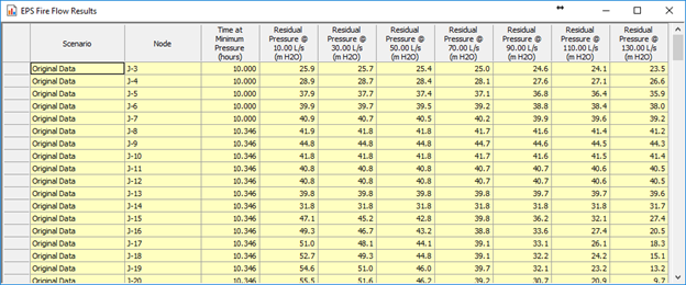
The first three (3) columns are always available showing the scenario label, the fire node label and the time at minimum pressure.
The remaining columns are based on the flow range set by the user. For each flow in the range the hydrant flow curve is calculated. The residual pressure is interpolated on this curve with the flow (specified in the column’s header). If the interpolation returns a negative pressure, (N/A) is shown in the table. Otherwise, any pressure greater than zero is displayed.
Units
The units used in the tool are based on the settings of the open project. You can change units by right-clicking the unit next to the minimum, increment and maximum fields on the main dialog and clicking "Units and Formatting". You can change the units of pressure in the results table by right-clicking the column header and clicking "Units and Formatting".
Other Notes
No changes are made to the project opened. When closing the tool or opening a different project, the project that was previously opened (if there was a project opened) is not saved.