Splicing Data
This section describes functionality in Bentley Fiber for creating detailed splicing diagrams in text or DGN file formats.
Default Splice Report
Default Splice Report at a Single Splice Location
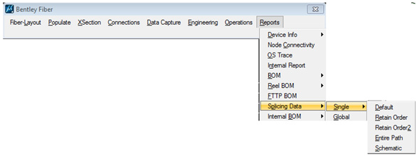
- From the Bentley Fiber menu, select Reports > Splicing Data > Single > Default.
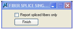
- The Fiber Splice Single dialog box opens.
- Activate the Report spliced fibers only check box to limit the report to spliced fibers.
- Select a splice on the map.
- Select a device or span on the map to be displayed on the left side of the splice report.
- Press Finish when completed.
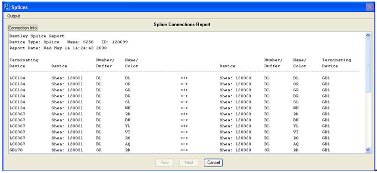
- The Splice Connections Report dialog box opens.
- The information contained in the dialog box can be written to a text file (.SPL), a graphic design file (.DSP) or placed on the cursor by selecting Output > Text File, Design File or Cursor.
Retain Order
This command generates a splice connections report showing fibers in buffer color order.
Create Text Output or Graphical Splice Reports, or *.csv Files to Import Into User Defined Templates
- From the Bentley Fiber menu, select Reports > Splicing Data > Single > Retain Order or Retain Order2.
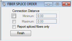
- The Fiber Splice Order(2) dialog box opens.
- Activate the Report spliced fibers only check box to limit the report to spliced fibers.
- Select a Splice on the design file. Identify the span to display on the left side of the report and press Finish to generate the report.
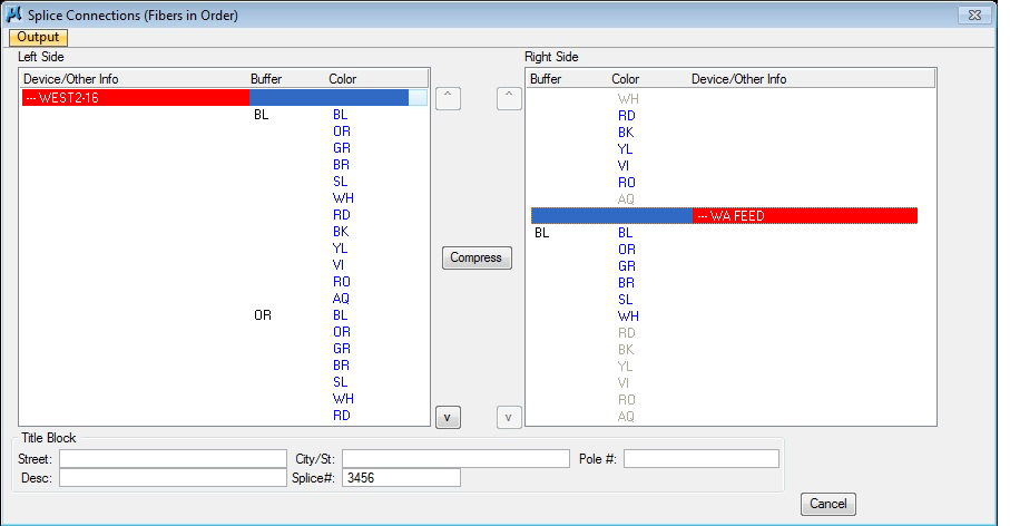
- The Splice Connection (Fiber in Order) dialog box opens.
- Select a fiber color to see the connection on the opposite side.
- Re-order the sheaths by selecting one sheath in the left or right side list and by clicking on the up or down icon.
- Key in the Title Block information so that it displays on the splicing diagram DGN when generated.
- The information contained in the dialog box can be written to a graphic design file (.DSP) by selecting Output > Text File. Note: The splice diagram drawing that is generated will, by default, display all buffers and fibers from the input side of the splice to any number of outputs present. The Compress option, if used, will compress the display of fibers to only display buffers if the fibers within those buffers are connected from sheath to sheath in a 1 to 1 manner.
By right clicking on the 'Output' button in the upper left corner of the Splice Connections dialog, the user has 3 options for Output files:
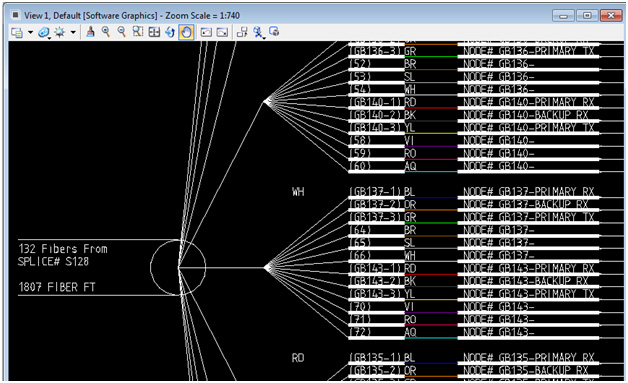
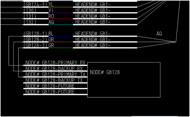
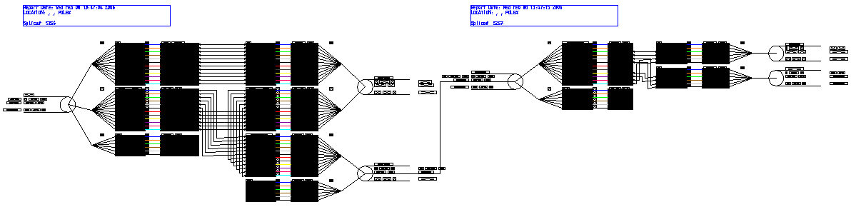
- Design File-this creates a Splicename.dsp file in the DGN folder of the project, by default-this is the graphical schematic showing the fibers, buffers, and node internals that are connected from that splice. (See diagram below.)
Note the node internals, also displayed in this graphic:
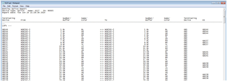
- Text file-this creates a splicename.txt file in the RPT folder of the project, by default, which shows the splice information in a text file format. (See diagram below.)
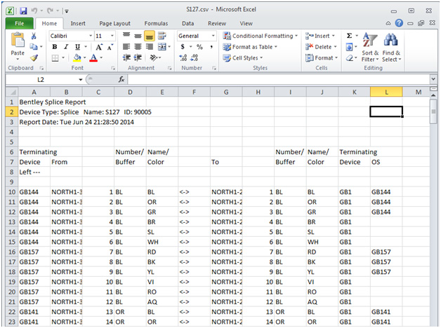
- CSV file-this option creates a splicename.csv file in the RPT folder of the project, by default, which can easily be imported to a spreadsheet. (See diagram below.)
Entire Path
The command generates a splice connections report showing fibers and connections throughout the entire path of the selected splice.
Create Entire Path Splice Connection Report
- From the Bentley Fiber menu, select Reports > Splicing Data > Single > Entire Path.
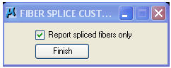
- The Fiber Splice Custom dialog box opens.
- Activate the Report spliced fibers only check box to limit the report to spliced fibers.
- Select a Splice on the design file. Identify the span to display on the left side of the report and press Finish to generate the report.
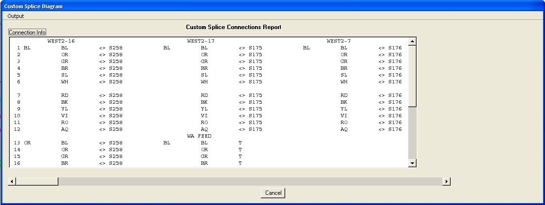
- A Splice Connections Report dialog box opens displaying the entire path of the highlighted splice.
- The information contained in the dialog box can be output to a text file (.SPL) or graphic design file (.DSP).
- Select Cancel to close the report window.
Schematic
This command generates a schematic fiber path throughout the entire network to all terminations of fibers from a given start point.
Generate a Fiber Schematic
- From the Bentley Fiber menu, select Reports > Splicing Data > Single > Schematic.
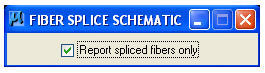
- The Fiber Splice Schematic dialog box opens.
- Activate the Report spliced fibers only check box to limit the report to spliced fibers.
- Select a Splice on the design file. Identify the span to display on the left side of the report and press Accept to generate the report.
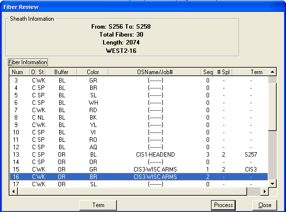
- A Fiber Review dialog box opens.
- Highlight a fiber in the Fiber Information list.
- Click Term to display the termination device. Note: The splice schematic drawing that is generated will, by default, display all buffers and fibers from the input side of the splice to any number of outputs present. The Compress option, if used, will compress the display of fibers to only display buffers if the fibers within those buffers are connected from sheath to sheath in a 1 to 1 manner.
- Click Process to create the schematic drawing. You must enter a name in order for the processing to occur.
Global
This command generates a splice connections report showing fibers and connections throughout the network.
Create Text or Graphical Global Splice Reports
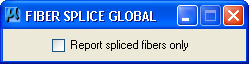
- From the Bentley Fiber menu, select Reports > Splicing Data > Global.
- The Fiber Splice Global dialog box opens.
- Activate the Report spliced fibers only check box to limit the report to spliced fibers.
- Select any device or segment on the extracted fiber network.
- The Splice Connections Report dialog box opens.
-

- Selecting Next or Previous displays connection information for each sheath. The connection report represents the highlighted sheath in the design view.
- The information contained in the dialog box can be written to a text file (.SPL), a graphic design file (.DSP) or placed on the cursor by selecting Output > Text File, Design File or Cursor. If Cursor is selected, you can resize the splice diagram by using the ACTIVE SCALE (AS=) commands.
- Select Cancel to close the dialog box.