Flows at Catchbasins
Although the type of flow is indicative of its origin (for example a rational flow probably comes from a catchment area), the Bentley stormwater products allow flow to be added from several source locations. CivilStorm also tracks flows and flow types as they progress through the system, making it easy to control and observe storm sewer flows.
Flow (and related) results are broken down into different groups in CivilStorm . The groups are:
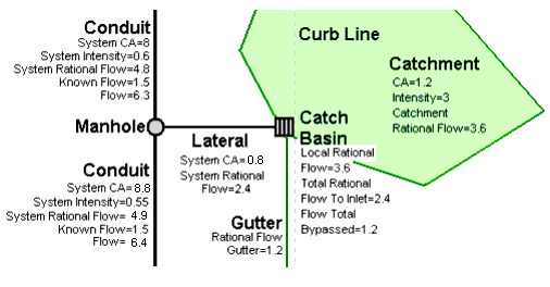
- System Flows - total flows in the subsurface (conduit) network, on the downstream side (outlet conduit) of a catch basin, manhole or transition node. The system flows are equal to the sum of the Local and Upstream flows.
- Local Flows - flows that occur at the catch basin inlet where the result is reported. For example the Local Rational Flow at catch basin is the 'rational flow' (i.e. catchment runoff computed using the Rational Method) generated by catchments that discharge directly to that catch basin.
- Inflow (Collection) - these flows enter at subsurface invert and is treated like carryover flow in the implicit and explicit sovlers.
- Upstream Flows - total flows in the subsurface (conduit) network, on the upstream side of a catch basin, manhole or transition node.
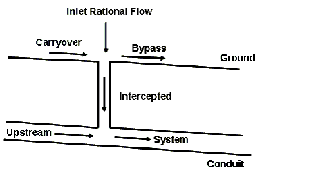
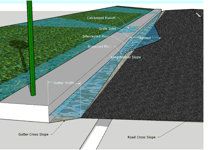
- Intercepted Flows - flows that are intercepted or captured by the inlet at a catch basin node.
- Bypass Flows - flows that are not intercepted by the inlet at a catch basin node, and continue on downstream via a gutter element
- Carryover Flows - flows at an inlet that were bypassed, via a gutter, from the inlet upstream.
- Total Inlet Flows - the sum of the Local and Carryover flows that reach an inlet via the surface network. In other words, the total flow that reaches an inlet. It does not include flows that enter the invert from upstream conduits.
In addition, the GVF rational solver from CivilStorm breaks flows down into different flow types. The types are:
- Rational Flow - catchment runoff computed using the Rational Method.
- Additional Subsurface Flow - flow added directly to the subsurface (conduit) network. This can represent a fixed inflow from a known source, such as an industrial discharge.
- Additional Carryover Flow - additional flow in the surface (gutter) network. This can represent gutter flow that bypassed an upstream inlet, where that upstream inlet is not included in the current model.
- Additional Flow - the sum of Additional Subsurface and Additional Carryover flows after they have mixed together in the subsurface (conduit) network.
- Known Flow - a flow where the total flow rate is known at various points in the system. A known flow downstream will overwrite (not add to) a known flow upstream. This can be used to represent flows derived from flow monitoring results.
- Fixed Flow - the sum of Additional and Known flows.
The major locations of load input and reporting are as follows:
- Surface Catchment Loads
- Surface Carryover Loads
- Inlet Approach Loads
- Inlet Captured (Intercepted) Loads
- Inlet Bypassed Loads
- Subsurface Piped Loads
- Subsurface External Loads
- Subsurface Total Piped Loads
Although input flow loads such as surface catchment loads and subsurface external loads are only editable for inlets, calculated loads, such as subsurface total piped load, are computed for all nodes.