V-Shaped Gutter Cross Section
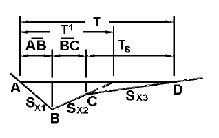
V-Shaped Gutter Cross Section
Equivalent cross slope (Sx) for V-Shaped gutter is found with the formula:
where:
Generally for on-grade inlets, spread is iteratively computed. In the case of a V-Shaped gutter, the Sx term considers the proportion of wet road and gutter surfaces. This is well documented in Example 4-4 on page 4-20 of Hydraulic Engineering Circular No. 22, Third Edition.
Then V-Shaped gutter depth can be inferred from spread with the following relationship:
d=T*Sx
where:
Conversely, for in sag inlets, the gutter depth is first computed and then the spread.
It should also be noted for V-Shape gutter that its cross sectional gutter flow area is computed geometrically with the computed on-grade gutter spread. The flow area is used to find the uniform flow velocity at the frontal interface with the grate inlet opening.
The gutter link is modeled as a channel in the implicit solver. The channel is internally modeled as a rating table of <Depth, Width> pairs for every 20% of Maximum Gutter Depth. That is 6 points (including <0,0> and <max gutter depth value, computed max gutter spread> points). This gutter-as-channel method is used to compute the upstream and downstream pairs of results: 1) Depth (In) and Spread/Top Width (Start) and 2) Depth (Out) and Spread/Top Width (Stop). The terms "Spread" and "Top Width" are used interchangeably even though "spread" refers the width of flow in a gutter, and "top width" is the same measurement but implicitly refers to a channel transect.
This holds true of GVF-Rational, SWMM, and implicit solvers: the software doesn't always compute a Depth and Top Width/Spread. It will always compute Top Width/Spread and Depth together, that is, if the software can compute the pair together at the upstream end the it will compute both of them. Otherwise, the software presents N/A for both of them. At the upstream/start end of gutter link the software computes depth and width of bypass flow in the gutter, right after inlet interception at the upstream node. If the upstream node of the gutter is a Catch Basin, and a physically defined HEC-22 type of catalog inlet, then the software computes these 2 results. Otherwise the software does not attempt to compute them (not having enough physical data to compute them at this time. At the downstream/stop end of the gutter link element the software will always refer to the gutter depth and gutter spread values at the stop node. Therefore, the stop node has to be a Catch Basin with a HEC-22 Inlet for these values to be computed and not appear as N/A.