Flow Definitions for Node Elements
This topic describes the following flow results:
Flow (Total In)
Flow (Total In) is the sum of all flows entering a node. This includes flows from:
- Incoming from Adjacent Links (Locally Added)
- Inflow (Wet) Collection
- Sanitary Loads Collection
- Captured Runoff
- Captured Additional Carryover (Rational Only)
- Known Flow (Non rational solvers do not support Known Flows)
- Additional Flow (Rational Only)
This result attribute is reported for the following element types:
And is calculated when using the following solvers:
- Explicit (SWMM Solvers)
- GVF-Convex (SewerCAD)
- GVF-Rational (StormCAD)
- Implicit (SewerGEMS Dynamic Wave)
Flow (Total Out)
Flow (Total Out) is the sum of all flows:
- exiting the node through links,
- exiting the system at the outfall,
- exiting the catchment as runoff flow.
Excluding all flow:
This result attribute is reported for the following element types:
And is calculated when using the following solvers:
- Explicit (SWMM Solvers)
- GVF-Convex (SewerCAD)
- GVF-Rational (StormCAD)
- Implicit (SewerGEMS Dynamic Wave)
Flow (Wet Weather Inflow)
Flow (Wet Weather Inflow) is the flows to the inlet of the node generated from the Inflow (Wet) Collection.
For Catch Basins, the Flow (Inflow Wet Collection) is not all necessarily captured by the inlet of the node. Some of it could be bypassed depending on the structure of the inlet.
Flow (Wet Weather Inflow) excludes catchment flow attached to the node.
This result attribute is reported for the following element types:
And is calculated when using the following solvers:
Flow (To Inlet)
Flow (To Inlet) is the total flow to the inlet of a node from the surface.
It includes:
Flow (To Inlet) is reported only for Catch Basin elements.
And is calculated when using the following solvers:
Flow (Local In)
Flow (Local In) is the sum total of all flows injected locally at the node at the current time step.
This includes:
- Captured Inflow Wet Collection
- Sanitary Collection
- Known Flows (Non rational solvers do not support Known Flows)
- Additional Flow (Rational)
- Captured Catchment Flow
And is calculated when using the following solvers:
The GVF-Rational (StormCAD) solver does not support dry weather (sanitary) inflows; a warning is given that sanitary inflows are ignored by the solver.
Flow Diagrams
The following diagram defines various flows.
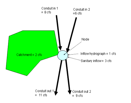
The values that appear in the property grid for the illustration are
- Flow (total in) = 20 (conduits+catchment+sanitary+inflow)
- Flow (total out) = 20 (conduits)
- Flow (local from inflow collection) = 1 (inflow hydrograph)
- Flow (local in) = 1 + 2 + 3 (capture + sanitary)
Another common use case is that of a catch basin where less that all of the flow is captured by the inlet. Given the flow in the illustration below and the assumption that the downstream conduit is not backing up and overflowing the catch basin, the following flows are defined:
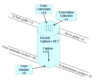
The values that appear in the property grid for the catch basin are
- Flow (Total in) = 37 (conduit in+capture+sanitary)
- Flow (Local surface) = 18 (catchment+gutter+inflow collection)
- Flow (Total out) = 37 (sum - gutter out))
- Flow (Local in) = 17 (capture + sanitary)
- Flow (Local from inflow collection) = 3 (inflow)
- Flow (Captured) = 0.667 (5+3+10) (flow to inlet times capture fraction)
- Flow (Overflow) = 0
For a more detailed description of flows at catch basins, see Location of Flows.