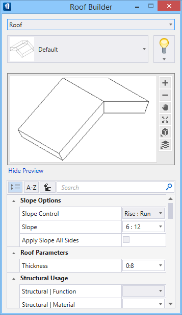
Roof Builder
 Used to create 3D solids
that represent common roof shapes including sloped, mansard, gambrel, hip,
shed, and profile roofs. The roof acts as an envelope that contains the 3D
solids.
Used to create 3D solids
that represent common roof shapes including sloped, mansard, gambrel, hip,
shed, and profile roofs. The roof acts as an envelope that contains the 3D
solids.
Note:
Placement is completed using the controls found on the
Placement ribbon tab and the
Property Panel which is loaded with the active
Building element catalog items and properties.
Accessed from:
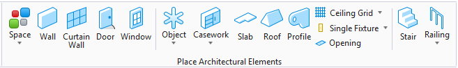
Note: This tool provides
the following features when creating roofs:
- When creating a roof, you first draw a shape to represent the roof footprint. Usually this is done in a top or isometric view. The roof also uses the ACS, enabling you to place an entire roof envelope on an angle.
- For sloped roofs, you identify which lines in the footprint define the roof pitch. and which outline edges create a slope.
- Roof forms slope away until they intersect the plane of another roof, forming a ridge. Slope base lines which intersect other base lines, extend sideways to meet the roof formed by the neighboring line. This forms hips and valleys in the roof.
- You frequently place roofs and then often times change the slope of a certain plane, or change the sides of the roof that have slope. This utility enables you to make changes to the slope of the roof. The ridges and valleys of the roof are updated during the process.
- The roof form can be extruded down from the top, or up from the bottom, and this displays in the tool settings Preview as well.
- All the forms inside a roof envelope have the same assembly. For example, all the joists in a sloped wood roof share the same construction and material. A sloped roof is constructed as one roof. All segments and sub-parts share the same function, material, and envelope.
- When a design calls for a roof to be constructed of different materials such as wood and steel, the wood roof portion and the steel roof portion are modeled as two different roofs with two different envelops.
Placement tab
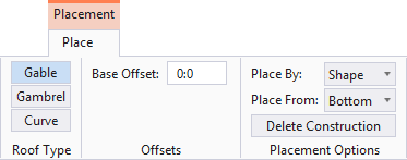
Note:
The
Placement tab opens on the ribbon when placing
Building elements. The
Placement tab contains settings specific to the
Building element being placed that are used to define the position, orientation
or dimensions of the Building element being placed. Also available on the
Placement tab, are a collection of Building
common tools selected specifically because of their relevance to the Building
element being placed.
Roof Properties
| Setting | Description |
|---|---|
| Catalog Type Selector | Used to select from available Catalog Types. Selections made here updates the Catalog Item Selector combo box. |
| Catalog Item Selector |
Used to select from available
Catalog Items. The
Catalog Item Selector combo box contains
several options and settings designed to make it easier to find the exact
catalog item you need to place/change.
The
Catalog Item list also includes user
defined assemblies, and RFA catalog items, if any.
|
| Catalog Tools |
A split button located to the right of the
Catalog Item Selector contains tools to
assist with managing catalog data prior to placement of selected catalog items.
Note: The
Save Catalog Item and
Save Catalog Item As... tools perform
administrative tasks on DataGroup System catalogs. Administrators and users may
want to hide the tool icons to avoid incidental or unwanted changes to their
firm's dataset by setting the user configuration variables
BB_CATALOGITEM_ADMIN_IN_PLACECMDS
and
BB_CATALOGITEM_SAVEAS_IN_PLACECMDS to "0", respectively.
|
| Preview |
Displays the selected catalog item in the preview
window. This display changes and the preview updates as various options are
chosen. A right-click in the Preview opens a
Show/Hide Viewing Tools option menu:
|
| Slope Options | Enabled for
Gable and
Gambrel roof types.
Note: An Alert
dialog displays
"There were errors creating roof, the roof may be
distorted. Do you want to continue?" when improper settings prevent one or
more roof panels, or the entire roof, from being created correctly. For
example, setting
Thickness to
0:0, because the materials used to create
any roof must have some sort of thickness. A partial roof may be created if you
continue, which can visually enlighten you as to what went wrong, and what
settings should be adjusted.
|
| Roof Parameters | |
| Structural Usage | Lists Structural usage properties. Structural function and material properties can be applied (if undefined) to active catalog items making them fully promoted Structural members. |
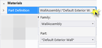
| Materials | Lists Part and Family definition assignments. Clicking in the Value column cell opens a Family and Part selection box. Here parts and families are available from the option menus. |
| Thermal Transmittance | Lists the thermal properties to apply to the active catalog item. |
| Identification | Lists identification properties for the active catalog item type. |
| Acoustical Parameters | Lists acoustical performance properties. The acoustic rating and test reference details are set here. |
| Fire Resistance | Lists fire rating properties based on agency fire safety tests and classifications. |
| Construction Phase | Lists design and construction phase properties for walls such as New Construction, Future Construction, and Items to be Moved. |
| Space Bounding | Lists properties that can be defined as True/False making the selected catalog item eligible for consideration during Building energy analysis. |
| IFC Override | Lists IFC properties not automatically mapped to DataGroup System properties that can be manipulated for export. |
| Classification | Building Classification Systems are supported by the DataGroup System. MasterFormat, OmniClass, and UniFormat property values can be associated with any Building element. Click the Value cell to open the Classification System selection combo box. The combo box is populated with selected classification system property values. It can be resized by clicking on the combo box's bottom right corner. Search for properties by name. Search results are displayed in the classifications hierarchy. Double click a property to select it. This action also closes the selection menu. The selected property displays in the selected classification system property value (on the Properties list). |

 (
( (
( (
( (
( (
( (
( (
( (
( (
(


Note:
Information in the
Value column rows can be completed by selecting
the applicable cell to activate an editor field, an option menu, or a pop up
dialog. This data is written to the element properties. Properties displayed
with grey text are read only. Some of these are set in the placement tool's
Placement tab, and can be modified there. The
dividing bar between the
Property, and
Value columns can be moved to change the width
of either area, or resize the dialog. A vertical and horizontal scroll bars are
available to scroll and adjust
Properties panel viewing and the display of
data.
Key-in:
Use the Catalog_Item argument to directly key-in the desired catalog item saved in the active DataGroup System catalog to pre-populate the tool settings. For instance ATFGENERATE ROOF Roof - 08 where "Roof - 08" is the catalog item name.
Note: The Catalog_Item argument
is case sensitive. Be sure to key it in exactly as it appears in the
catalog.
Note: This
tool is enabled only when the
MDL
application
ROOFBLDR is loaded. Selecting the tool
icon automatically loads the application. Because
ROOFBLDR is not loaded by default when
starting
AECOsim Building Designer, the key-in
listed for this tool will not respond if keyed in before using the tool icon.