| File name
|
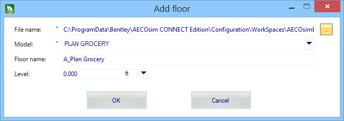
Used to enter the path to the referenced floor plan document
(typically a DGN model or DWG/DXF file). The referenced floor plan document
contains the graphical elements representing walls, partitions and wall
openings such as windows and doors. These referenced elements can then be used
to Trace or Define the walls of a room for instance.
- [...] - Opens
the Open
dialog to browse the disk floor plan files.
Note:
Imported DWG/DXF units – Distances in a DWG/DXF
file are defined in drawing units rather than meters or feet. You must know the
units which were used to create the DWG/DXF file. AECOsim Building Designer establishes the distance
units based on the extent of the DWG/DXF file’s drawing width and height.
|
| Model
|
If the referenced floor plan document is a DGN file that
contains multiple models, they are listed in the provided
Model drop list. The selected the DGN model
is then referenced into your project building.
Note: The Model
setting is disabled when the selected reference document file is of a type that
is not a DGN file.
|
| Floor name
|
Used to enter a name for the new floor. By default, the floor is
named using the selected floor plan document reference’s file name or DGN model
name.
|
| Level
|
Locates the floor by specifying an elevation value (Z axis).
|
| OK
|
Completes creating the new floor, and closes the Add floor tool
settings. The new floor the appears in the AECOsim Energy Simulator Project
Tree, and is eligible for adding zones and rooms.
|
| Cancel
|
Closes the Add floor tool settings window without creating a new
floor.
|
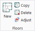
 Used to create new floors. As no
floors exist on a
new
blank project, a floor must be added by importing files with floor plans
from DGN models, DWG/DXF files, PDF files or image files. No useful work can be
carried out until at least one floor is set up.
Used to create new floors. As no
floors exist on a
new
blank project, a floor must be added by importing files with floor plans
from DGN models, DWG/DXF files, PDF files or image files. No useful work can be
carried out until at least one floor is set up.