To create a compound cell
For most types of fixtures, furnishings, and equipment (FF&E), compound cells should be used because they incorporated both the 3D representation used for modeling and rendering and the 2D symbolic representation used for drawings. These are created using the Compound Cell Manager and they are stored in *.BXC libraries.
The task below places the graphical elements that will comprise the compound cell in the DGN file. The elements can be forms and/or plain drawing elements.
-
 Select the Compound Cell
Manager tool (or Key In:
TFDIALOG COMPOUND CELL).
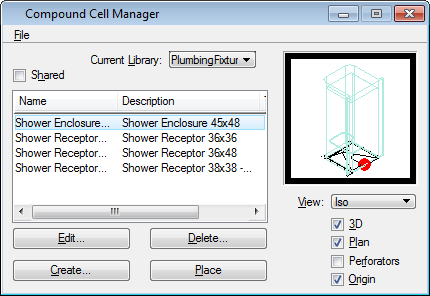
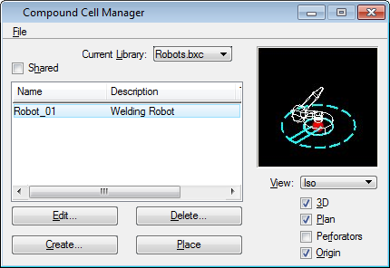
Opens the Compound Cell Manager dialog.
Select the Compound Cell
Manager tool (or Key In:
TFDIALOG COMPOUND CELL).
Opens the Compound Cell Manager dialog.
-
Select the
menu.
Opens the Create Compound Cell Library dialog.
-
In the
Save In path, navigate to the compound cell
library destination folder (in this example, we navigate to
\AECOsimBuildingDesigner\Workspace...\support\dataset\cell).
Enter
Robots.bxc for the File name.
Click Save to create the compound cell library.
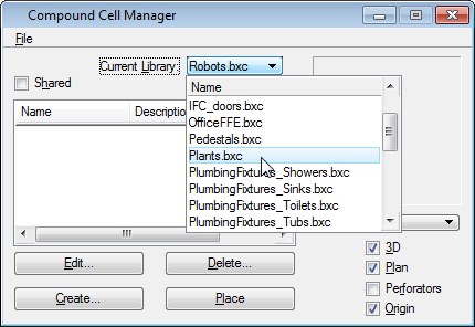
- In the Compound Cell Manager, open the Robots.bxc cell library from the Current Library drop down menu.
-
In the Compound Cell Manager click
Create... to open the Create Cell dialog.
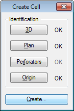
In the Create Cell dialog, complete the following:
- Click
3D and identify 3D graphics, preferably a
3D cell.
The OK next to the 3D button turns black.
- Click
Plan and identify 2D graphics, preferably
a 2D cell.
The OK next to the 2D button turns black.
- If the compound cell
needs to punch holes through walls or slabs, click
Perforators and identify a shape to be
used as perforator.
The OK next to the Perforators button turns black.
- Click
Origin and identify the origin of the
Compound Cell with a data point.
The OK next to the Origin button turns black.
- Click Create... to open the Compound Cell Info dialog.
- Click
3D and identify 3D graphics, preferably a
3D cell.
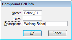
- In the Compound Cell Info dialog, enter a Name, Type (optional), and Description (optional) for the new cell. Click to add the new compound cell to the cell library.