Design Wall Design Group 1

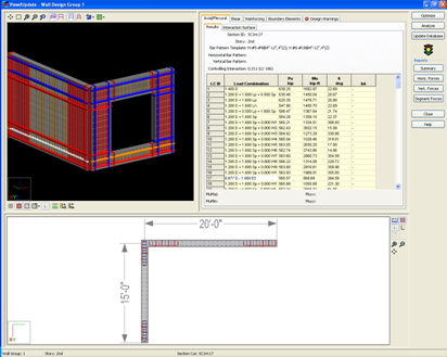
When the View/Update dialog opens, use the target cursor to select a section cut for which results will be displayed. The selected section cut will be highlighted in orange. At the top of the wall is a group of buttons that allow you to zoom and alter the keyboard and mouse functions. Familiarize yourself with these buttons. In the bottom portion of the screen you will notice the manual reinforcement you entered earlier displayed graphically.
Review Axial-Flexural Design Results
- Select Axial/Flexural from the back row of tabs. This is the default and most likely already selected.
- Select Results from the front row of tabs.
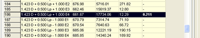
The axial-flexural design results for the selected Section Cut are displayed in tabular form in the screen to the right. Each row in the spreadsheet corresponds to a load combination. Above the spreadsheet is a summary of the design, including information on the controlling load combination.
The locally (Mumaj, Mumin) and globally (Muxx, Muyy) oriented required moments for the selected load combination is then displayed below the spreadsheet.
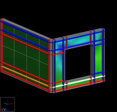
- Once the Section cut has been selected and a load combo chosen, you can view the wall stresses from RAM Frame.
- At the bottom of the graphics screen select the show/hide mesh button. Then click the next one called mesh options.
- Notice that the wall now has a stress contour.
- In the mesh options menu you will see several stress types to select from. Take this opportunity to switch between them and see the behavior of the program. The stresses correspond to the load combos at a section cut, so changing the section cut and combo will yield different results.
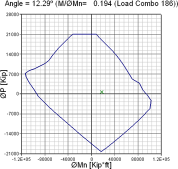
- Select Interaction Surface from the front row of tabs.

The axial verses flexural plot that is shown corresponds to the angle resulting from Mumaj and Mumin for the selected load combination, referred to as the β angle.