Slab Edges
The slab overhang is the distance from where the slab is laid out to the slab edge. For slab edges laid out along beams, this is the distance from beam centerline to slab edge.
When there is a complete network of beams, as is the case for One-way floor systems, the easiest way to model slab edges is to use the Whole Perimeter option. If there is just one diaphragm on the floor type, this will place the slab edge around the building perimeter at the specified slab overhang.
If there is more than one diaphragm on a floor type, a message box will appear asking that a perimeter beam or wall be selected to identify the desired diaphragm. The target cursor is then available for beam/wall selection. Once a beam/wall is selected, a slab edge will be placed around the selected diaphragm at the specified slab overhang.
In order to use this command, it is necessary that the framing be properly defined. If the framing is not properly defined a warning message will appear and no edges will be added. This command cannot be used when the floor framing lacks a complete perimeter loop of beams as is common for Two-way slabs.
It is not necessary for the slab edge to be on the perimeter of the framing; the slab edge may cut into the building. In such instances the edges may be entered with the Whole Perimeter command and edited to produce the desired edge definition.

Individual sections of slab edge may be laid out using the Add option. With this option, first click on the point where this segment of slab edge is to begin, then click on the point where this segment of slab edge is to end. The slab edge distance may vary along the length of a beam (i.e., there may be multiple segments of slab edge along a single beam, or the slab edge distance at one end may be different than that at the other end). When a slab edge is laid along a line that contains multiple beams, the edge is automatically split up into multiple segments (one for each beam).
Slab edge assignments are made by clicking on a SnapTo point, a column, or a point along a beam or wall that defines the beginning of the slab edge, and then likewise clicking on a point that defines the end of the slab edge. Proceed in that manner around the layout until the area to be assigned a slab or deck is enclosed by a slab edge. As the slab edge is laid out, a line will appear on the screen to show where the boundary has been defined. Care must be taken to ensure that the slab edge is placed on the proper side of the beam; when the slab edge distance is greater than 0.0, the default setting requires that the slab edge be laid out in a clockwise direction to assure that the slab edge is placed on the outside of the beams.
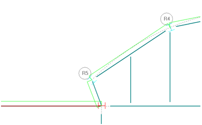
The first of following figures shows a slab edge laid out with respect to the beams. The second figure shows a freeform slab edge laid out using SnapTo points.

To change the slab overhang of an existing slab edge, specify the new overhang value and use the Change command. Alternatively, merely lay down a new slab edge over the old with the Add command; it is not necessary to delete the old slab edge first.
To move a slab edge that was laid down in the wrong location or that needs to be moved to accommodate framing changes, use the Move command, select a slab edge segment, and move one end or the other to the desired new location. Alternatively, delete the segment and re-add it using the Add command.
The Layout - Slab - Slab Edge command must not be used to specify slab openings.