Analysis of Tilt-up Walls
Modeling of Tilt-up Walls
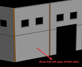
A tilt-up wall is a special type of wall that includes gaps with adjacent members. In RAM Modeler, a tilt-up wall can be defined with a gap at either side of wall. The purpose of defining a gap is to provide analytical separation from adjacent members (i.e., wall does not transfer any force and it acts independently).
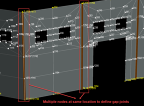
Once a tilt-up wall with gap is defined in the modeler, RAM Frame internally creates a special analytical model for the wall in such a way that gap-joints between the wall and adjacent member are ensured in analysis. This is accomplished by creating multiple analytical nodes at gap-joint locations and the program connects the wall and adjacent members to these nodes properly so that the wall and adjacent member are disconnected. This process is fully automated by the program and therefore, there is no need to create any physical separation between the wall and adjacent member in RAM Modeler.
A tilt-up wall gap is visually identified with an orange-colored-line drawn on sides of wall where gap is defined (see the figure below). In addition, invoking the command View – All Node Numbers shows finite element nodes at locations where multiple nodes are created to define gap-joints (this is available either after analysis or by invoking Process – Rebuild Mesh Data command).
Creating a valid analytical model for a tilt-up wall with gaps is important to have accurate results for design of tilt-up wall system. To this end, RAM Frame enforces the following rules to make sure a valid analytical model is created for a tilt-up wall:
- If a wall marked as tilt-up wall with gap in the modeler, RAM Frame creates special gap-joints between the wall and its adjacent member. Gap-joints are created if and only if adjacent member is either a lateral column or a lateral wall.
- If a wall marked as tilt-up wall without gap, RAM Frame does not create gap-joints. This means that wall and adjacent member are fully connected.
- If two tilt-up
walls have a gap defined between them and if there is a beam framing into the
walls at the gap location, the following error message is given when analysis
is started:
Beam X on Story Y is framing into walls where all walls have gap assignments.
This error message indicates that neither wall supports beam. - If eccentric moment is applied at a location where two-tilt-up wall with gap-joint exist, the program equally splits moment among tilt-up wall joints.
In addition, the following limitations are important to note
- If the option
Include Rigid Link at Fixed Beam-to-Wall Locations
is selected in
Criteria – General
dialog, the program creates a special link between beam and wall
to provide more accurate force transfer between them. However, this command is
ignored if wall is a tilt-up wall with a gap at the location the beam is
framing. The following warning message is included in the
Analysis Log file:
Failed to include rigid link at fixed beam-to-wall location for wall X on story Y and beam Z on story S
because the wall has a gap-joint defined at the same location.
- It is allowed to connect or disconnect a node from diaphragm by invoking Assign – Nodes – Diaphragm Connection command. If the command is called for a node located on a tilt-up wall gap-joint, the program enforces the command for all nodes found at the same location.
The Nodal Displacement report shows displacements of all nodes (including multiple nodes created to model gap-joints) for analyzed load cases if the option Reports – Include Results for All Nodes is selected.
The command Process – Results - Reactions is used to display reactions at foundation nodes. If multiple nodes created to model gap-joints at foundation level exist, reaction for each node is displayed. Similarly, the program shows reactions at the multiple nodes in Reaction report.
Advanced Analysis for Models with Tilt-up Walls
The advanced analysis feature is an elastic second order analysis intended to be used primarily for the out-of-plane analysis of tilt-up walls. Currently, the feature is only available if structural model includes a tilt-up wall and there is Strength or Service type load combination created in RAM Frame Load Combinations module. Advanced analysis involves solution of analytical model for each Strength or Service load combination with including nonlinear effects (i.e., geometric nonlinear effects).
Custom Load Combinations
For Custom Load Combinations, the program still uses superposition principle (that’s combo results obtained by superposing individual results from each load case in combo).
Strength and Service Load Combinations
The program provides an advanced analysis solution developed for analysis of models with tilt-up walls. In this solution, each Strength and Load Combination is run separately within an iterative solution to account for nonlinear effects. This is known as 2nd order analysis since nonlinear effects (such as geometric nonlinear effects) are directly considered within the solution. It is important to know that 2nd order analysis results are not superposed results: they include effects of all load cases at once and they include nonlinear effects directly. This approach is in contrast with superposed combo results in which first order analysis results of load cases are superposed and artificially amplified to account nonlinear effects. On the other hand, it should be noted that running each combo separately in an iterative solution scheme extends analysis time depending on size of analytical model.
After Strength and Service load combinations are iteratively analyzed, results are available in the reports similar to those reported for superposed combo results. In addition, Strength and Service combo results can be displayed on screen by invoking commands available in the Load Combinations module.
Cracked Factor for Service Load Combination
| = | ||
| = |
Live-Load Reduction for Strength and Service Load Combinations
Live-load reduction can be optionally applied to Strength and Service Load Combination results (see Criteria – Advanced Analysis dialog in the Load Combinations module). If the option is selected, the program considers live load reduction for load combinations with reducible live load case. The algorithm computes a live load reduction factor for each member force in each advanced analysis load combination by comparing the reduced and unreduced forces for the same load combination with superimposed load cases.
Locking Diaphragm for Analysis
It is possible to lock diaphragm displacements during analysis for a lateral load case. This feature is optional and it can be set in RAM Modeler (see Prob Table – Lateral Load Cases command in elevation view). If the option is selected for a nodal or wall pressure load case, RAM Frame prevents diaphragm lateral movements when the load case is analyzed. The purpose of this feature is to isolate out-of-plane behavior and prevent loads intended to be used for out-of-plane analysis from being transferred into the diaphragm and creating in-plane forces in adjacent walls. If a Strength or Service load combination includes a load case with diaphragm locked, the program also enforces it during analysis of model against the load combination.
Conditions for Which the Advanced Analysis Feature is Not Available
The advanced analysis feature is currently offered only in RAM Frame - Load Combinations module. There are some cases for which the feature is not available. These cases are enforced to prevent instabilities in the iterative analysis and inconsistencies in the load case and load combination finite element models:
- If there is
no tilt-up wall in model, the advance analysis is not allowed, and the
following message is reported:
No Tilt-up Wall is Found in the Model. Advanced Analysis is Canceled.
- If
out-of-plane stiffness of lateral wall is not included, the advance analysis is
not allowed, and the following message is reported:
Out-of-Plane Stiffness is Required for Wall(s). Select the option to include out-of-plane stiffness
for walls in RAM Frame Analysis - Criteria - General.
- If the
option
Exclude Buckling Restrained Braces from the Gravity Load
Case Analysis is selected (see
Criteria – General
in Load Cases module) and if there exists Star Seismic,
CoreBrace or any other type of buckling restrained brace in model, the advance
analysis is not allowed, and the following message is reported:
Buckling restrained brace stiffness cannot be ignored in the advanced analysis. Remove the option to
exclude buckling restrained brace from the gravity case analysis in RAM Frame Analysis - Load Cases
mode - Criteria - General.
- If the
option
Include Out-of-Plane Stiffness - For Semi-rigid
Diaphragms with Two-way Decks for Lateral Load Cases is not
selected (see
Criteria – Diaphragm
in Load Cases module) and if there is a semi-rigid
diaphragm with two-way deck in model, the advance analysis is not allowed, and
the following message is reported:
Two-way slab stiffness cannot be ignored in the advanced analysis. Select the option to include
out-of-plane stiffness for semirigid diaphragms with two-way decks for lateral load cases in
RAM Frame Analysis - Load Cases mode - Criteria – Diaphragm
- If the
option
Include Out-of-Plane Stiffness - For Rigid Diaphragms
with Two-way Decks for Lateral Load Cases is not selected (see
Criteria – Diaphragm
in Load Cases module) and if there is a rigid diaphragm
with two-way deck in model, the advance analysis is not allowed, and the
following message is reported:
Two-way slab stiffness cannot be ignored in the advanced analysis. Select the option to include
out-of-plane stiffness for rigid diaphragms with two-way decks for lateral load cases in
RAM Frame Analysis - Load Cases mode - Criteria - Diaphragm.
Recommendation for Convergence Problems Encountered with the Advanced Analysis Solution
In some rare cases, it is possible that the program may not produce results for some Strength and Service combos if iterative solution fails to convergence for those combos (i.e., the solution cannot numerically satisfy equilibrium equations). It is possible that there would be no solution at the level of combo loads applied or there would be modeling issues that prevents solution to converge. If such a situation is encountered, the following remedies are recommended to resolve convergence problems:
- Check analytical model is properly restrained.
- If instability is reported for a node, investigate end-releases of members connected at the node.
- In some cases, cause of instability may be related to insufficient member stiffness in certain direction such as lack of out-of-plane stiffness for walls or for diaphragms.
- Check load on members does not exceed buckling capacity of members (i.e., compare load on member against member Euler buckling load). If buckling load capacity of a member is exceeded, it is possible that the iterative solution runs into a converge problem (i.e., due to local instability encountered in member.)
- If model includes some members extremely stiff and some others extremely flexible, this may also cause numerical instability issues, so solution may fail to convergence.
- By default, the convergence tolerance is set to 1.0e-5 (see Criteria – Advanced Analysis dialog in the Load Combinations module). The tolerance value is used to check whether numerical solution is converging (i.e., equilibrium equations are satisfied numerically). In some cases, the default tolerance value may be too stringent to prevent convergence. A larger tolerance (i.e., 1.0e-4 or 1.0e-3) can be used. However, this step should be taken cautiously because using a large tolerance value may help solution to converge but also may lead to inaccurate results. Therefore, modifying the tolerance value would be the last resort to solve convergence problems.
- The dialog Criteria – Advanced Analysis provides additional troubleshooting for convergence problems (i.e., number of increments and iterations). Increasing number of increments and\or iterations might be another solution to overcome convergence problems.
2nd Order Analysis: Nonlinear Solution of Structure
Nonlinear effects are important to account for during analysis if structure exceeds linear-response threshold. Nonlinear effects are grouped into two categories: geometric and material effects.
Geometric nonlinear effects are caused from member undergoing large displacements/rotations. The P-Δ effect (P-large delta) and P-δ effect (P-small delta) are two most-known sources of geometric nonlinear effects in structural engineering. On the other hand, material nonlinear effects arise when member material response surpass linear behavior threshold. Typical examples are yielding of steel member/bar or cracking of concrete member.
| = | ||
| = | ||
| = |
- The P-Δ (P-large delta) geometric nonlinear effect is related to second-order moments caused by axial forces acting through relative transverse end displacements associated with member chord rotation
- The P-δ (P-small delta) geometric nonlinear effect is due to second-order moments within axially loaded member caused by axial forces acting through the member displacements relative to their rotated chords
| = |
| = | ||
| = |
For frame type members (i.e., beam, column and brace), the program calculates KG matrix based on current state of member (i.e., forces and moments within member at current iteration). Further information about derivation of KG can be found at the following reference: Matrix Structural Analysis, William McGuire, Richard H. Gallagher and Ronald D. Ziemian, 2nd Edition, Wiley, 2000.
| = |
It should be mentioned that geometric stiffness matrix for shells used to model diaphragms is turned off (i.e., no nonlinear effects considered in shells used to model diaphragms).
Currently, the program only considers geometric nonlinear effects. This means that material nonlinear effects are not directly considered within advanced analysis. On the other hand, such effects are indirectly considered by stiffness modification factors such as crack factors selected for concrete walls and diaphragms.