Column Gravity Forces
ACI 8.8.1 stipulates, "Columns shall be designed to resist the axial forces from factored loads on all floors or roof and the maximum moment from factored loads on a single adjacent span of the floor or roof under consideration. Loading condition giving the maximum ratio of moment to axial load shall also be considered."
To implement the second requirement of ACI 8.8.1 "Loading condition giving the maximum ratio of moment to axial load shall also be considered", RAM Concrete considers the effect of each individual live load case (see Section 3.3.10 for how load cases are computed) on each axis of the column. Note that if the user selects not to skip load live loads (see Section 2.5.2) then this code provision will not be implemented and the column force from all live loads applied at the same time will be computed for use in the column mode design.
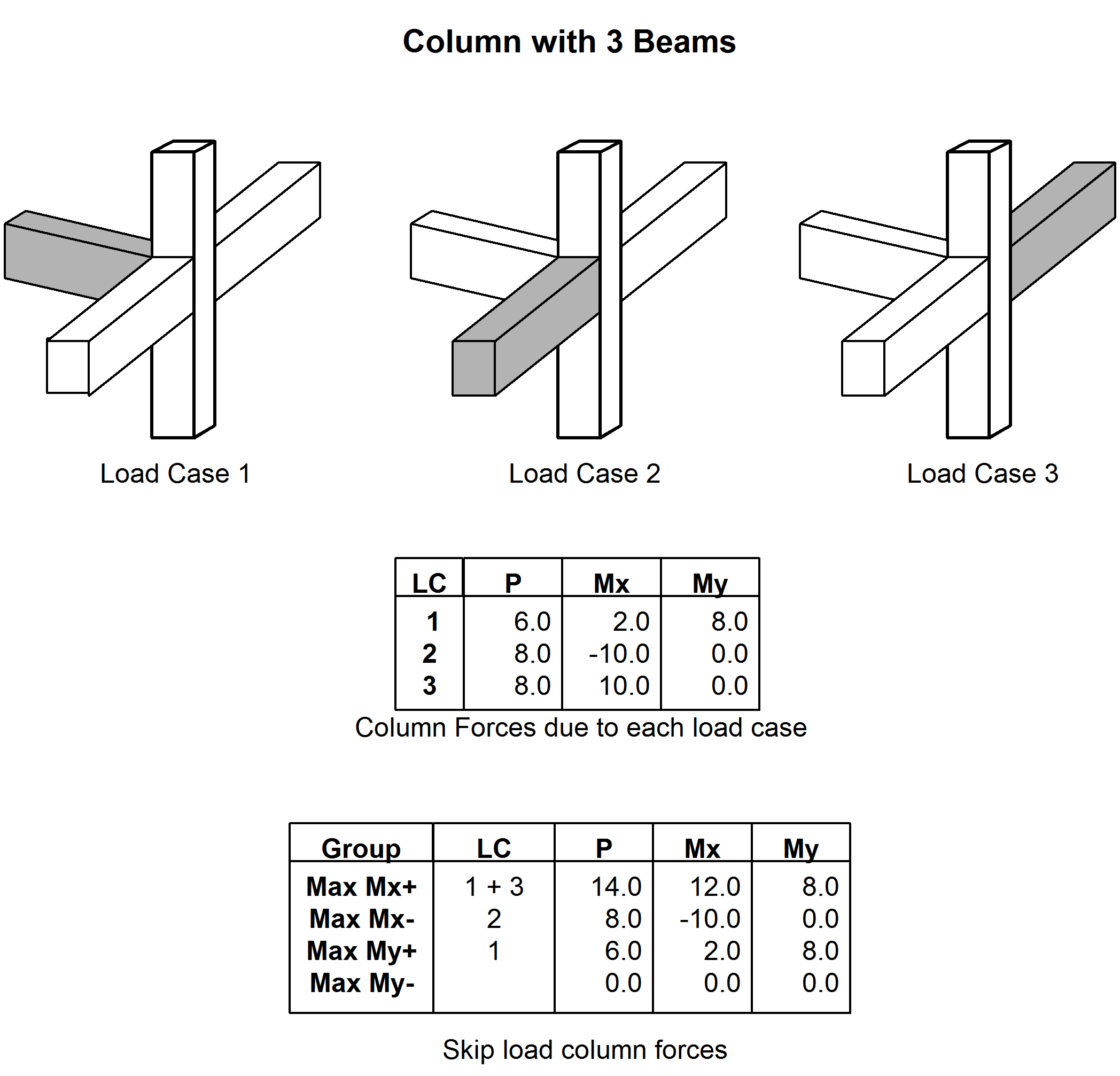
When considering skip loading the program computes the column moments for each column for each live load case. It accumulates forces into four groups based on the sign and axis of the moments. In other words, there are four groups of design forces, one for positive major axis moment, one for negative major axis moment, one for positive minor axis moment and one for negative minor axis moment. For a particular live load case, the program determines which two (one for each axis) of these groups the forces fall in. It then adds all the moments and the axial load, reduced by the appropriate live load reduction factor (see Section 3.3.9) to that group. In this way the program calculates the absolutely largest moment about each axis of the column and accumulates the associated other axis moment and axial forces (irrespective of direction). As this process is performed for both top and bottom of the column the program effectively calculates eight gravity live load force points for each column. Figure 3-15 shows a simple example for calculating forces at the top of a column, which is subject to three live load cases.
The program also tracks one additional axial load that is the column axial load due to all live load cases, irrespective of column moment direction. This axial load is used in determining the design column forces in the Concrete Column mode to meet the first requirement of ACI 8.8.1. Important, in the event that a single stories column is broken into multiple finite elements (can only be due to openings that intersect the column) the axial force from the lowest finite element in the column will be utilized in the design. Refer to the Wall Openings and Meshing section in the technical notes for more information in the Finite Element Mesh.
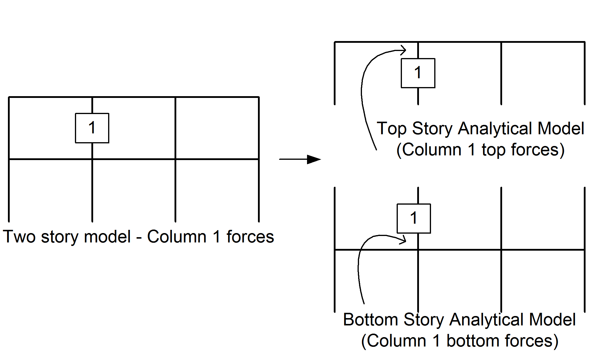
As the program analyzes the structure one story at a time the program cannot calculate the column top and bottom forces from the same analysis. As illustrated below for column 1, the column top forces are calculated from the analysis at which the column top is at the story level being analyzed. For the column bottom the forces are taken from the story analysis where the column bottom is at the story being analyzed.
For Dead and Roof Live Load cases there is no skip loading and all the loads of these load types are considered to occur simultaneously on a story and the single set of computed column forces is utilized in the Column Design mode.
As column forces are calculated from top and bottom of the column in separate analyses, the associated gravity shear force depends on which load pair (top and bottom) is assumed to occur at the same time. The grouping of load pairs to obtain the largest shear force is described in more detail in the RAM Concrete Column manual. Note that column forces are always recorded at the depth of the deepest beam framing into the column (see Rigid End Zone Section 3.4.13). This is true for all cases except for lateral columns, which are pinned by the user at the level of the story.
All the computed column forces for each column can be viewed in the Column Forces Report (see Section 5.9).
Column Slenderness
Much of the information required to perform slenderness calculations is obtained in the Analysis Mode. However, the actual application of the slenderness calculations is performed in the Concrete Column Design mode. As such the description of the effect of slenderness, including Sidesway and Effective Lengths, on the design column forces (data points) is described in detail in the Concrete Column Manual.